Electrical construction
Princip of function we explain on a LUXAR 11W lamp. Circuit contains supply section, which includes interference suppressor L2, fuse F1, bridge rectifier from 1N4007 diodes and filtering capacitor C4. Starting section includes D1, C2, R6 and diac. D2, D3, R1, R3 have protect function. Other parts have normal operation function.

Lamp start
R6, C2 and DIAC mades first pulse to base of transistor Q2 and cause his opening. After start is this section blocked by diode D1. After every opening of Q2 is discharged C2. There is not possible to collect enough energy for reopening of diac. Next are transistors excitated over very small transformer TR1. It consists of ferrite ring with three windings (5 to 10 coils). Now are filaments powered over capacitor C3 from voltage rises from resonant circuit from L1, TR1, C3 and C6. Than the tube lights up is resonation frequency specified by capacity of C3, because he has much lower capacity than C6. In this moment is voltage on a C3 over 600V in a relation to used tube. During start is peak collector current about 3 to 5 times bigger than during normal operation. When the tube is damaged, there are hazard of transistor destroying.
Normal operation
When the gas is ionisated in a pipe, C3 will be practically shorted and thanks to this frequency goes down and changer is now drived only by C6 and changer generates much lower voltage but enough to keep the light on. In a normal situation, when transistor opens, that current to TR1 increasing until his core is saturated and next his feedback to base drop away and transistor closes. Now opens second transistor which is excitated by reversly connected windind of TR1 and all process repeats.
Failures
Common failure is broken capacitor C3. it is possible mainly at cheap lamps, where are used cheaper components for lower voltage. Whet the pipe doesn't lights up on time, there are risk of destroying transistors Q1 and Q2 and next resistors R1, R2, R3 and R5. When lamp starts, changer is very overloaded and transistors usually doesn't survive longer temperature overloading. When the pipe serve out, electronics is usually destroyed too. When the pipe is old, there can be overburned one of filaments and lamp doesn't lights up anymore. Electronics usually survives. Sometimes can be pipe broken due to internal tension and temperature difference. Most frequently lamp fails, when power on.
Repair of electronics
Repair of electronics usually means change of capacitor C3 if he is brobek. When burns fuse, probably will be damaged transistors Q1, Q2 and resistors R1, R2, R3, R5. You can replace fuse with resistor 0R5. Failures can be multiplied. For example, when is shorted capacitor there can be thermally overloaded transistors and will be destroyed. Best transistors for replacing of original types are MJE13003, but it is not easy to find them. I replaced them with BD129, but they are not available now. There exists other variants like a 2SC2611, 2SC2482, BD128, BD127, but I am not sure if they will be long-life. Original transistors are not available on our market. If doesn't matter size of case TO220, it's possible to use transistors MJE13007.
Mechanical construction
Lamp is usually compounded of two parts. One is plastic cover with holes for pipe and bills. Tube is agglutinated to it. Second much bigger piece has slots for bills from the inner side. Inside is printed circuit board with components and wires from tube. From the upper side of PCB are wires to top of lamp, where are soldered or stamped to the contact. Both plastic parts are clicked to himself and sometimes glued. Usually you can carefully leverage with a small screwdriver sequently to round to the gap between both plastic pieces for releasing of glue. Next you must leverage more to the opening lamp. For closing of lamp you can only click both plastic pieces to himself. Look at photo of opened lamp.
Reviewing
Most of these compact fluorescent lamps use same or very similar wiring. more expensive lamps use a little complicated wiring with electrode preheating and thanks to it they have longer lifetime. Repairing of these lamps not pay off, because price of cheaper types are very low now and price of human work is much higher. Wiring diagrams originates while repairing of lamps and they are only for study or repair uses. Informations are from retracing of lamps and from sources in a link section.
Links
-
https://www.simandl.cz/stranky/elektro/starter/starter.htm Page with a description of electronic starter in a Czech language. -
https://eu.st.com/stonline/books/pdf/docs/3706.pdf ST | ELECTRONIC FLOURESCENT LAMP BALLAST
Schematics and photos
Bigluz 20W
Compact fluorescent lamp Bigluz 20W use classic wiring with a small changes. Values of parts are modified for bigger power.

Photo of opened lamp Bigluz 20W.
Isotronic 11W
Lamp Isotronic 11W use a little modified wiring, where doesn't exists starting circuit with a diac. Lamp starts probably thanks to capacitor C1.

Luxtek 8W
Lamp Luxtek 8W use classic wiring with a small changes. Interesting is only thermistor, which probably makes light start and filament preheating.
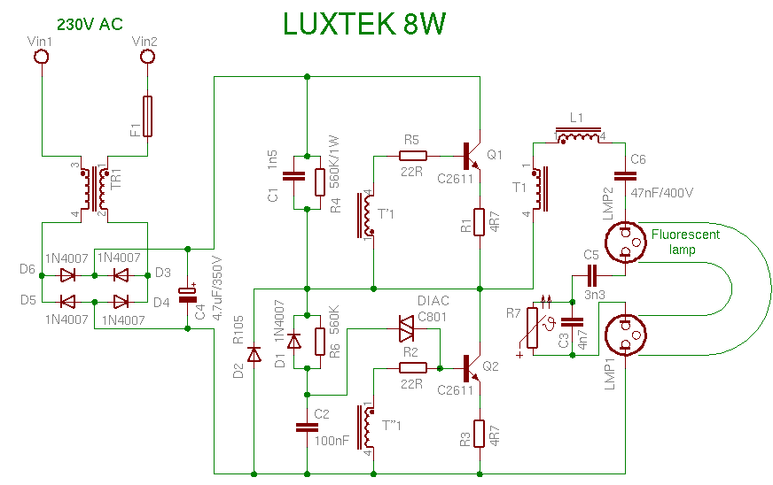
Photo of board with a electronics and upper side of cover.
Maway 11W
Lamp Maway 11W use different wiring too like Isotronic lamp.

Maxilux 15W
Lamp Maxilux 15W use classic wiring.

Polaris 11W
Lamp Polaris 11W has a small thread and changes some values of components. Wiring is classic.

BrownieX 20W
BrownieX 20W lamp has a simplified wiring like a Isotronic lamp.

PHILIPS ECOTONE 11W
Lamp PHILIPS ECOTONE 11W use again simplified wiring like a Isotronic lamp. This lamp compared to other has a right dimensed components, that electronics probably can live longer. Wiring is less cheated than others. It has coil L2 for blocking HF interference and capacitor C1 for voltage 1200V, which is very much stressed. Tube is superior compared to a no-name types. Light color "warm white" brings light of classic bulb and doesn't have a small pink tone like others. Tube is a little longer and have much light compared to others 11W types. All these lamps, which I have from several series have identical color tone and brilliance. Compared to lamps MAWAY, where every item have different color tone, some have destroyed electronics, some have pipe with a lost vacuum etc... It is seen, that lamps from marked manufacturers have guaranteed parameters and better quality than no-name.

Photography of opened Philips lamp.
IKEA 7W
Lamp IKEA 7W has classic wiring like a Luxar 11W. Component values are modified to a lower power. Parts are enough voltage dimensed. Failure was overburned one of filaments. Lamp was on continuous for one year, which is over 8500 hours. Life time corresponds to a label specifications.

Photography of opened lamp IKEA 7W
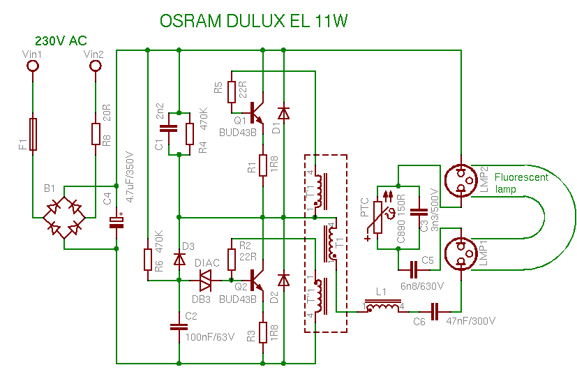
OSRAM DULUX EL 11W
Lamp OSRAM DULUX EL 11W has again classic wiring with only few changes. She has a small thread and was a fully functional.
OSRAM DULUX EL 21W
Lamp OSRAM DULUX EL 21W has a classic wiring diagram. In contrast to a previous OSRAM lamp doesn't have thermistor for slow start. She has overburned one filament.

EUROLITE 23W (October 13 2008)
Lamp EUROLITE 23W has a classic wiring diagram. For schematics thanks to Mard.

SINECAN 5 2x 26-30W (October 13 2008)
Electronic ballast SINECAN 5 for two fluorescent tubes has identical circuit like most of compact fluorescent lamps. Little differency is in powering tubes before D6 diode and wiring of start capacitors C10 a C11 about tubes. I don't understand exactly why this is wired this way. Ballast doesn't have fuse, but only thin wire. Ballasts was broken due to blowed electrolytic capacitors. It breaks transistors and resistors R3, R4, R5 and R6.

Photography of open ballast.
IMMEDIATELY 25W (24.3.2010)
This bulb is only interesting with power value 25W. Circuit is classic.

PHILIPS GENIE 11W (24.3.2010)
Philips Genie bulbs I am using for many years. I am satisfied with them. Their advantage is very compact size of tube which allow installing in to the lamp with small space for bulb. It lights up immediately after power-up. I didn't see any negative effect on their lifetime.

Disassembled light bulb.
PHILIPS GENIE 14W (October 22 2010)
This bulb has almost identical circuit to their 11W variant. It has two additional protect dioded D6 and D7. Values of few components are a little changed. Transistors are more powerful types 13003.

Электронный балласт
https://woodocat.livejournal.com/38695.html
µLB — это простой и миниатюрный электронный балласт для ламп дневного света. У себя дома я везде заменил старые стартерные схемы на эти, еще ни одна лампа не сгорела. Балласт выполнен на основе широкораспространенной микросхемы IR2153(D). И имеет следующие преимущемтва перед обычной стартерной схемой:
-
отсутсвует мерцание при работающей лампе; -
плавный запуск лампы, с предварительным прогревом нитей накала увеличивает срок службы; -
уменьшается размеры индуктивности и габариты в целом; -
полностью исключен фальстарт; -
отсутсвует слабое звено — стартер; -
запуск не превращается в нервотрепку;
Я встречал много подобных схем, и изготовил несколько разных вариантов. Последний вариант, пожалуй, самый удачный. В первом варианте я использовал кольцевые магнитопроводы. Выбор именно кольцевых магнитопроводов был серьезной ошибкой — очень сложна намотка, тем более при малых габаритах колец. Настроить удалось только после долгого и мучительного перебора емкостей. Второй вариант платы содержал клеммники типа ТВ-02 под винт, которые занимали много места.
Не буду повторяться, принцип работы данной микросхемы хорошо описан в разных источниках. Прототипом моего электронного балласта стала схема с сайта radioradar.net. Схема заработала сразу, но не стабильно. Некоторые номиналы элементов на той схеме, на мой взгляд, указаны некорректно. Мощность, рассеиваемая сопротивлением R2 (68к) на той схеме, превышает 1 Вт... Резистор сильно разогревается, теряется стабильность и лампа гаснет. А ток продолжает протекать через R2... и нагрев продолжается... Определенно, это может закончиться пожаром! Кроме того, в затворах полевых транзисторов стоят слишком большие сопротивления, заряд на затворах полевых транзисторов плохо рассасывается, в итоге опять же сильный нагрев полевых транзисторов, лампа гаснет, транзисторы продолжают разогреваться... Поэтому, первым делом необходимо увеличить мощность и велицину сопротивления R2, а сопротивления R3 и R4 уменьшить с 200 Ом до 22 .. 47 Ом. В статье указана частота 33 кГц, хотя для указанных номиналов она составляет 40 кГц.
После некоторых экспериментов и простых расчетов получилось следующая схема:

Сопротивление R1, это балластный токоограничительный резистор, мощность которого должна быть не менее 1 Вт. Чем меньше сопротивление R1, тем больше рассеиваемая на нем мощность. Оптимальные сопротивления — 100к (2 Вт) или 200к (1 Вт). Другое узкое место — емкость между нитями накала С8. Эта емкость - составляющее звено цепи резонанса. С одной стороны для разогрева желательно иметь как можно большее значение емкости, с другой строны для возникновения хорошего резонанса выбирать эту емкость слишком большой нельзя. Для ламп разного типа необходима подстройка схемы - подбор емкости С8 и индуктивности L1.
Схему можно усовершенствовать, если параллельно конденсатору C8 включить термистор с положительным ТКС — РТС позистор. В холодном состоянии сопротивление позистора мало, и ток разогревает электроды лампы. Вместе с электродами разогревается и позистор. При определенной температуре сопротивление позистора резко повышается, цепь разрывается, и индуктивный выброс зажигает лампу. Позистор шунтируется низким сопротивлением горящей лампы. Использование позистора позволяет лампе зажигаться плавно и снижает износ электродов, что продлевает срок службы лампы до 20 тыс. ч.
Также вместо предохранителя FU1 можно установить терморезистор с отрицательным ТКС (NTC). Он ограничивает бросок тока через диодный мост, при зарядке конденсатора С1 во время включения балласта в сеть. В правильно настроенной схеме ничего не нагревается, и радиаторы для транзисторов не нужны (при мощности лампы до 20 Вт).
Разрабатываем топологию.
Приступаем к намотке дросселей - 220 витков проводом 0,2 мм.
Модули запаяны, входной дроссель склеиваем сразу без зазора и обматываем "шашечным" желтым скотчем.
Выходной дроссель нуждается в подстройке. Этой палочкой устанавливаем веричину немагнитного зазора. Обратите внимание - предохранитель пока не запаян.
Настраиваем балласт по наиболее яркому свечению лампы.
<предыдущая страница